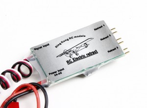
 While working on one of my DIY projects, I’ve ordered some really nice retracts with linear actuators from HobbyKing, available here. As soon as I got that cool stuff from them, I realized that the controller (picture on the right) did not work like I would like it to. Although it would fit most RC projects, my demands from it were a tad different.
In the original scenario, the controller is hooked onto one of your receivers channels, and would drive the retracts connected to it according to the PWM signal it receives – which are in most cases translated from a stick position on your remote, or a state of a button.
In my case, I wanted the controller to retract or extend upon receiving a signal from a GPIO, and pinging back, to another GPIO, whenever the requested action is finished. I had several options to approach this problem:
- Buy another controller
- Find a way to download the program from this controller, reverse engineer it, and change to my needs
- “Reverse engineer” the circuitry, and build a new program for it, accommodating my needs
Well, option 1, was quickly dismissed because it’s not cool. and opstions 2 and 3 depend on the fact that there is an easy programmable IC on this thing. So, of course the next step was to tear the heat shrinking tube from it, and take a look at what’s inside.
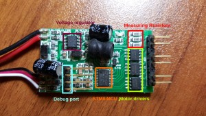
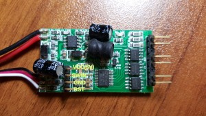
Observing the picture above, we can see an STM8 MCU (stm8s003f3) from ST, which after examining it’s datasheet has some kind of ST proprietary debug port called SWIM. Well, this is something to work with! After examining the board once more time, I noticed that the debug port and other pins needed for debugging are actually laid out on the PCB to a header which is not soldered (The picture is from after I soldered it).
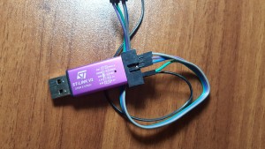
Marked on the image are the meanings of each pin on the header that I soldered. Now that we know where and how to tinker with the MCU, we need an actual ST programmer to do something useful with it. After searching the internets for a while, I found that there is a cheap ST-Link/V2 programmer sold on eBay for a couple of bucks, and of course I ordered it.
You guessed right! This is the ST-Link/V2 programmer! It connects to your PC via USB and has several debugging interfaces for ST MCU’s – we only need the SWIM one, which also requires a connection to the reset pin of the CPU – to issue a reset once a new program is loaded. The programmer also provides Vcc (both 5v and 3.3v) which you can use to power the controller.
I’m not going to go through driver installation here, there are plenty of options to choose from – official support on various versions of Windows as well as several opensource projects which provide support for Linux.
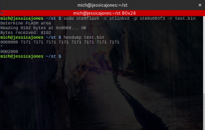
Of course, as you can see, the first thing I tried to do is dump the current firmware from the MCU, but with not much success, the MCU program memory appears to be locked, and upon unlocking it will wipe itself. This rules out option 2, and we are left only with option 3, which is, “reverse engineering” the PCB and writing new firmware for it. Challenge accepted!
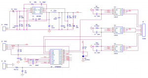
NOTE: Not all the numbers correlate to the actual PCB
Now, as you can see, this is the final drawing of the PCB after I examined every part of it. The main stuff is the MCU (obviously), the three L9110 motor drivers that actually drive the connected retracts, and measuring resistors, which are used to measure consumption of the retract motors and stop them (when they can’t move anymore, and start drawing more power).
Now for the software part! I used IAR to compile and debug (I found no good STM8 debuggers for Linux, enlighten me!), and I owe a big thanks to Mark Stevens, on his blog he has some excellent writeups on STM8 programming (I have to confess: I’ve never programmed for an MCU/embedded before). After a lot of playing around, and debugging, I’ve finished with a working firmware with operates in the following way:
- Listens for a signal to retract or extend on respective GPIO’s
- Upon receiving a signal, clears the finished GPIO
- Performs the requested operation on each retract ouput until:
- Retracts are in needed position
- Timeout reached (no retract connected)
- Sets the finished GPIO to HIGH
The core parts of the new firmware are:
- main.c
- As the name states – the main part of the firmware, which does all of the initialization:
- Configuring the CPU prescaler
- setting up GPIO’s
- enabling interrupts
- As the name states – the main part of the firmware, which does all of the initialization:
- globs.c
- Defines some usable names for the GPIO ports we are using
- Defines global variables used throughout the firmware
- control.c
- interrupts.c
- The firmware I wrote, is based mostly on interrupts to accomplish it’s tasks, the interrupts include:
- Timer interrupt (used for periodic check of power draw once retract/extend operation is started)
- GPIO interrupts – to sense when we are requested to do stuff
- ADC interrupts – used for measuring the power draw (tl;dr ADC = Analog-to-Digital converter, converts the voltage on the measuring resistors to a number, which we can use in calculations)
- The firmware I wrote, is based mostly on interrupts to accomplish it’s tasks, the interrupts include:
Well, I think that mostly it. Pretty long this time, hope you could learn something from this. If you have some question, or suggestion, please do comment 🙂
Of course, the code is fully available on GitHub, want to use it? Go for it!
https://github.com/sandler31/STM8-Retract-Driver
P.S. If you’re wondering what is the REF stuff in the code, and the 2.5V that is generated to one of the ADC pins, I don’t really have an idea – I thought at first it was some kind of reference for the ADC to measure with more accuracy (The default reference for it is Vcc, which is 5V), but I haven’t found a way to use it. It might have been used in some other version of the board, or in some way I haven’t found (No option to specify ADC reference voltage in this specific STM8 MCU to my knowledge). Anyway, the measurement is pretty precise even without a lower reference on this MCU – not much jitter at
